Loading…
Micro-Wind Systems · DAWT architecture
Remote power, built around wind.
Continuous generation for infrastructure operating beyond the grid.
The Coevo DAWT architecture captures distributed wind energy in a compact, enclosed turbine designed around remote infrastructure applications. It generates through the night, through the season, and through the weather that suppresses solar — behind a structural enclosure rather than on an exposed surface.
Configure
Choose a size. See the numbers.
Three configurations share one platform. Select one to see its nameplate rating, modeled generation, and the applications it is built around.
300W
Nameplate power
- 498 Wh/day
- Modeled generation at 5 m/s average wind
- 87 W
- Modeled output at 10 m/s (22 mph)
20.8 W equivalent average continuous generation
Instantaneous power
Typical application
Remote infrastructure and multi-load field compounds
Designed for continuous remote power generation where solar alone may not provide sufficient reliability or operating hours. Coevo's primary remote-power configuration and the centre of the product family. Designed for continuous remote generation where solar alone may not provide sufficient reliability or operating hours.
Modeled performance
Product family
Three sizes. One platform.
DAWT 150W · DAWT 300W · DAWT 450W. The DAWT 300W is Coevo's primary remote-power configuration and the centre of the family.
DAWT 150W
Compact
150W
Nameplate power
249 Wh/day
At 5 m/s avg wind
44 W
At 10 m/s (22 mph)
Best for
- Low-power remote equipment
- Sensors
- Monitoring
- Small communications loads
DAWT 300W
Primary
300W
Nameplate power
498 Wh/day
At 5 m/s avg wind
87 W
At 10 m/s (22 mph)
Best for
- Remote infrastructure
- SCADA / RTUs
- Oil & gas monitoring
- Telecom
- Industrial instrumentation
DAWT 450W
Higher output
450W
Nameplate power
746 Wh/day
At 5 m/s avg wind
131 W
At 10 m/s (22 mph)
Best for
- Higher-power remote loads
- Communications
- Industrial monitoring
- Larger battery systems
- Multi-device installations
Preliminary engineering configuration. Modeled generation derives from CFD report TR-26-0019; nameplate ratings and output figures remain subject to validation through wind-tunnel and field testing. Physical dimensions, weights, generator specifications, cut-out and survival wind ratings, and certification status are not final and are not published.
Primary configuration
Built around the DAWT 300W.
Coevo's primary remote-power configuration combines a 300W nameplate DAWT with continuous, low-wind energy generation designed around the power requirements of remote infrastructure.
At a 5 m/s average wind condition, the current modeled system generates approximately 498 Wh over 24 hours, providing continuous energy input to the site's power system. At 10 m/s (22 mph) wind speed, modeled output reaches approximately 87 W. The 300W rating is the nameplate at the rated operating condition — not a continuous output.
- 300W
- Nameplate power
- 498 Wh/day
- At 5 m/s average wind
- 87 W
- At 10 m/s (22 mph)
- 20.8 W
- Equivalent average continuous
Modeled performance
Power at a moment. Energy over a day.
Output rises steeply with wind speed and reaches nameplate at 15 m/s (34 mph). The daily energy figures describe something different — what the unit accumulates over 24 hours at an average wind condition. Both are modeled, and both matter when sizing a system.
Modeled performance
Modeled performanceAverage output across 24 hours, against the site's average wind speed. Hover the chart to read any site.
A site that averages 5 m/s does not blow at 5 m/s — it varies. Because power follows the cube of wind speed, the windier hours contribute far more than the calm ones take away, so the day average sits well above what an unvarying breeze at the same speed would produce.
Approved performance points — DAWT 300W
Energy · Wh/day
498 Wh/day
At a 5 m/s average wind, over 24 hours — 20.8 W equivalent average.
Average · W
20.8 W
Averaged over 24 hours at a 5 m/s average site.
Power · W
300 W
Nameplate, at the 15 m/s (34 mph) rated condition.
Watts (W) are power at a moment. Watt-hours per day (Wh/day) are energy accumulated over 24 hours. A DAWT 300W is a 300 W nameplate machine that is modeled to generate 498 Wh over a day at a 5 m/s average wind — the two numbers describe different things.
Modeled performance, not measured results. Output is derived from the aerodynamic performance measured in CFD report TR-26-0019 (September 2026), applied at sea-level air density with an assumed 80% generator and charging efficiency. Power follows the cube of wind speed, so doubling the wind is roughly eight times the power, and output reaches nameplate near 15 m/s (34 mph). Daily and average figures are evaluated across a Rayleigh wind speed distribution at a 5 m/s (11 mph) annual mean — below the lowest standard small-wind class in IEC 61400-2, which sets Class IV at 6 m/s — on the distribution basis IEC 61400-2 and AWEA 9.1 specify. These are modelled design-basis figures pending wind-tunnel validation; they are not field-validated, certified, or measured production numbers.
Side by side
| Specification | DAWT 150W | DAWT 300WPrimary | DAWT 450W |
|---|---|---|---|
| Nameplate | 150W | 300W | 450W |
| 5 m/s modeled generation | 249 Wh/day | 498 Wh/day | 746 Wh/day |
| Output at 10 m/s (22 mph) | 44 W | 87 W | 131 W |
| Position | Compact | Primary | Higher output |
Preliminary engineering configuration. Modeled generation derives from CFD report TR-26-0019; nameplate ratings and output figures remain subject to validation through wind-tunnel and field testing. Physical dimensions, weights, generator specifications, cut-out and survival wind ratings, and certification status are not final and are not published.
Applications
Start from the load, not the hardware.
Pick an application to see which configuration typically fits. This is an exploratory starting point — real sizing follows the site.
Oil & Gas
Typical fit
DAWT 300W or DAWT 450W
DAWT 300W
300W
- At 5 m/s avg wind
- 498 Wh/day
- At 10 m/s (22 mph)
- 87 W
DAWT 450W
450W
- At 5 m/s avg wind
- 746 Wh/day
- At 10 m/s (22 mph)
- 131 W
Wellpad and pipeline instrumentation typically runs several concurrent loads on one battery bank, which is the condition the primary configuration is built around.
Loads in this class
SCADA and RTUsTank and pressure monitoringCathodic protectionMethane detection
Selection depends on load, battery autonomy and local wind conditions. These are exploratory starting points for a sizing conversation, not engineering guarantees — final configuration follows a site review.
Talk through a siteWhy wind, here
Power that shows up when nothing else can.
An energy platform designed to provide power when solar cannot — nights, storms, winter, dust, and shade. Providing consistent charge to keep batteries healthy and operations active.
Continuous generation day and night
Reduced dependence on sunlight
Reduced battery cycling
Reduced deep cycling
Continuous trickle charging
Smaller required battery reserve in appropriate applications
Complementary operation with existing solar systems
Remote operation
Rugged enclosed turbine architecture
Low-maintenance generation
Designed for mission-critical infrastructure
Generation during poor solar conditions
Benefits are design intents subject to site conditions and validation through testing and pilot deployments. No specific battery-life extension is claimed.
System integration
The turbine is one part of the kit.
Each configuration anchors a complete Remote Power Kit — turbine, power management, storage, and protected output — so the whole system arrives specified together rather than assembled on site.
One kit per configuration
- DAWT 150W Remote Power Kit150W
- DAWT 300W Remote Power Kit300W
- DAWT 450W Remote Power Kit450W
Protected energy capture
Safety begins with controlling the moving system.
Surrounding the rotor with a protective structure is what lets Coevo pursue sites where exposed rotating machinery is unsuitable or restricted — and it is why generation happens behind a structure rather than on an exposed surface. These are engineering intents, each subject to validation of the complete assembly.
- Reduced direct access to rotating blades
- Potential containment of damaged rotor components
- Reduced wildlife contact exposure
- Reduced risk from exposed rotating machinery
- Potential reduction of conventional blade-throw concerns
- Better fit for compact sites
- Greater control over ingress
- Application-specific screening options
- Cold-weather mitigation opportunities
- Protection of internal components
The enclosure is not only a safety feature — it is what makes the machine work
With the diffuser vanes removed, calculated power collapsed to zero at every rotor speed tested: vortices shed from the housings shifted the apparent wind direction and reversed the torque. The result held when the analysis was repeated in a larger computational domain at a higher wind speed. The diffuser recovers that energy and delivers a far steadier torque signature, which simplifies generator matching and power electronics.
Computational analysis only. Not yet validated in hardware.
Physical access and guarding
Opening size and rotor standoff must be engineered together — there is no single universal “safe opening” dimension. Small openings may prevent finger or hand access; larger slots require greater standoff; very large openings may be treated as full-body access. Mounting height changes the applicable guarding considerations, and OSHA guarding duties and ISO reach-distance standards must be considered together, particularly for rotating systems mounted at or below seven feet.
Wildlife
Wildlife risk varies by site and species, and no single opening size establishes universal compliance. Screening may reduce access, but site assessment remains necessary. Some bats may pass through openings around 3/8 inch, and for birds the governing dimension is body cross-section rather than wingspan. Enclosure may materially reduce direct rotor exposure — it does not guarantee wildlife approval.
Ice and cold weather
Enclosure may reduce external blade-icing exposure, but inlets and outlets remain open for airflow and internal ice can still accumulate. Detection, shutdown behavior, anti-icing measures, drainage, and containment may all be needed depending on climate. Cold-weather design remains under engineering review.
Design principles
What the platform optimizes for.
Battery-first value
The platform is designed around battery-backed field assets, not around a headline generation number. The objective is a healthier state of charge across the day, not peak output in a gust.
Protected energy capture
Generation happens inside a structural enclosure rather than on an exposed surface. The rotor is shielded from weather, debris, and site hazards — a durability argument solar panels cannot make.
Solar replacement or complement
Designed to run as a standalone charging source or alongside existing solar and battery systems, adding generation for the hours and seasons when solar output is reduced.
Modular serviceability
Being developed so that bearings, rotor, generator, and shroud components can be serviced or replaced individually in the field rather than replacing a complete system.
Harsh-environment design
Configurable environmental packages target dust, salt spray, cold weather, storm loading, and high-altitude operation. Protection levels are engineering targets, not certified ratings.
Omnidirectional by design
A vertical-axis rotor inside a diffuser accepts wind from any horizontal direction, so there is no yaw system to align, drive, or maintain.
Diffuser-Augmented Wind Turbine
What DAWT means, in plain terms.
DAWT stands for Diffuser-Augmented Wind Turbine. Coevo's Micro-Wind system uses a DAWT-style architecture intended to improve wind capture in a compact, enclosed form factor for remote infrastructure and battery-backed field assets.
Coevo's Micro-Wind architecture is designed to use a compact diffuser and enclosure approach to support wind capture in remote, industrial, and infrastructure-based environments. The rotor is an enclosed-blade vertical-axis design, and the surrounding shroud has been engineered with an integrated diffuser intended to improve blade protection and low-wind performance. Aerodynamic gains are design intent and remain subject to wind-tunnel validation.
What the architecture is intended to do
- Improve wind capture in a compact form factor
- Protect the blades behind a structural enclosure
- Support low-wind performance at typical field sites
- Accept wind from any horizontal direction, without yaw
- Enable deployment where open blades are restricted
Aerodynamic performance gains from the diffuser are design intent and remain subject to wind-tunnel validation.
How it works
From moving air to monitored power.
Six stages carry wind energy from the shroud to the battery — and report on themselves once they get there.
Capture
An enclosed-blade vertical-axis rotor inside a diffuser shroud, designed to accept wind from any horizontal direction without yaw control.
Convert
Generator configurations sized per model, converting rotation into raw electrical output.
Condition
Power electronics condition variable generation into stable, battery-safe charging.
Store
Integration with battery-backed field systems — the load class the platform is built around.
Monitor
Optional telemetry reports generation, state of charge, and system health to operations teams.
Maintain
A field-serviceable, modular approach intended to allow a part swap instead of a system replacement.
System flow
Wind
Diffuser shroud
Enclosed rotor
Generator
Power electronics
Battery / local load
Monitoring and control
High-level architecture only — detailed engineering configurations remain confidential.
System anatomy
Every component, engineered for the field.

Select a component to see its role in the platform. The diagram is a high-level engineering concept — detailed internals remain confidential.
Engineering concept animation
Rotor
The enclosed vertical-axis rotor — the turning element at the centre of the unit.
Designed to support
The equipment that keeps infrastructure running.
Filter by category to explore the load classes the platform is being developed to support.
Showing 76 of 76 load classes.
- SCADA and RTU systems
- Pipeline telemetry
- Tank level monitoring
- Custody metering stations
- Flow meters and flow computers
- Industrial control panels
- Cathodic protection monitoring
- Wellhead pressure and temperature sensors
- Gas and methane leak detection
- Valve position monitoring
- Chemical injection controllers
- Rotating-equipment vibration monitors
- Corrosion and integrity probes
- Weather stations
- Environmental monitoring stations
- Soil moisture and agricultural sensors
- Air quality monitors
- Stream and river gauges
- Rainfall and snowpack sensors
- Water quality sondes
- Seismic and geotechnical instruments
- Wildlife and trail cameras
- Irrigation and pump control
- Utility telemetry
- Distribution fault indicators
- Recloser and switch controllers
- Substation perimeter monitoring
- Lift-station telemetry
- Reservoir and tank-level telemetry
- Pressure-reducing valve monitoring
- Grid sensor nodes
- Leak detection and acoustic loggers
- Transportation sensors
- Rail wayside monitoring
- Bridge structural monitoring
- Dynamic message signs
- Traffic counters and classifiers
- Grade-crossing monitoring
- Road weather information systems
- Culvert and slope monitoring
- Avalanche and rockfall detection
- Marine navigation aids
- Buoy telemetry
- Tide and wave gauges
- Dock and pier monitoring
- AIS transponders
- Lock and channel sensors
- Security systems
- Remote alarms
- Perimeter intrusion detection
- Surveillance cameras
- Gate and access control
- Site lighting control
- Asset and equipment trackers
- Smart infrastructure
- Dam and levee monitoring
- Right-of-way monitoring
- Landfill gas monitoring
- Construction site monitoring
- Remote lighting and signage
- Mine bench and tailings instrumentation
- Low-power communications
- IoT gateways
- Field communications
- LoRaWAN and mesh gateways
- Cellular backhaul radios
- Repeater and relay stations
- Satellite terminals
- Two-way radio infrastructure
- Emergency field systems
- Defense-related field systems
- Deployable command posts
- Incident-area communications
- Early-warning sirens
- Temporary monitoring stations
- Disaster-response telemetry
Environmental configurations
Configured for the site, not the showroom.
Standard
Baseline configuration for temperate, non-classified sites.
Wet and coastal
Corrosion-resistant materials and drainage targets.
Dust and industrial
Ingress-focused screening and filtration targets.
Cold-weather
Icing detection, drainage, and low-temperature operation targets.
High-altitude
Density-adjusted performance modeling and thermal targets.
Storm-prone
Elevated survival-load and shutdown-behavior targets.
Marine
Salt-spray exposure and marine-grade material targets.
Classified-location development configuration
Development track toward classified-area assessment of the complete assembly.
Environmental protection targets and available configurations will depend on final product design and certification.
Battery support
Shallower cycles. Healthier batteries.
The conceptual comparison shows how supplemental wind input may reduce depth of discharge versus battery-only and solar-plus-battery systems — lifting the overnight floor that drives battery wear.
Illustrative modeling only. Battery life depends on chemistry, temperature, cycling, charge control, load, maintenance, and operating conditions — no battery-life percentage is guaranteed.
Battery-support contribution
% state of charge · illustrativeConceptual 72-hour comparison of battery-only, solar + battery, and solar + battery + wind. Illustrative only — not a battery-life guarantee.
Aerodynamic analysis
Where the air actually goes.
CFD analysis lets the program evaluate rotor geometry, diffuser and shroud interaction, and wake behavior in simulation — resolving design questions long before a prototype is cut.
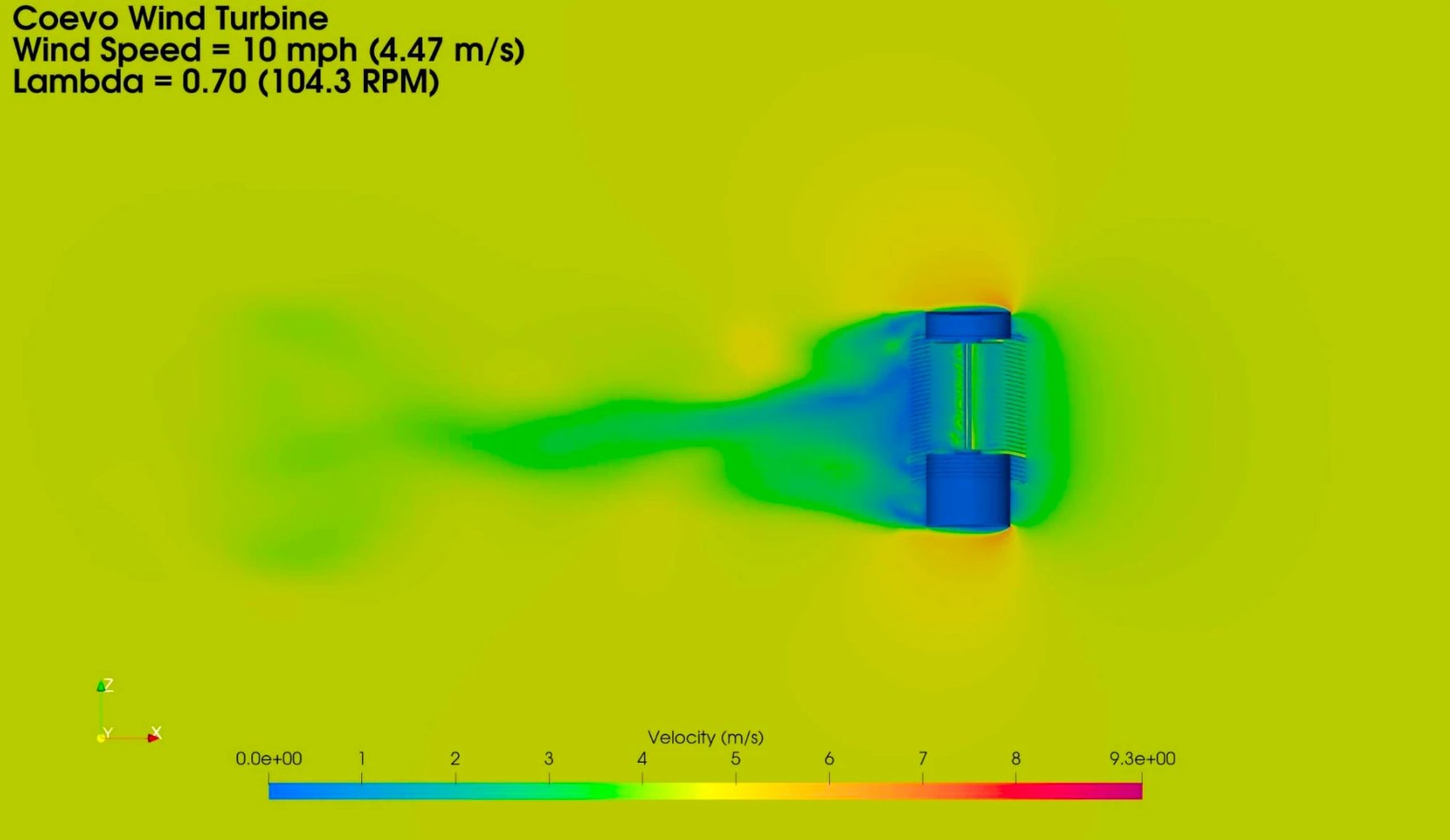
CFD · Aerodynamic analysis · TR-26-00194.47 m/s (10 mph) · λ 0.70 · 104.3 RPM
Velocity field — elevation section
A vertical slice through the complete assembly at 4.47 m/s (10 mph). Air enters through the louvered shroud, works on the rotor, and exits downstream as a long wake — while the housings above and below sit in near-still air.
How to read it
Shows how the protective enclosure shapes flow into and out of the rotor.
Computational analysis of a development rotor configuration. The aerodynamic performance measured in TR-26-0019 is the basis for the modelled output figures shown elsewhere on this site. Simulation is not a substitute for instrumented power-curve testing; wind-tunnel validation follows.
Engineering development
Built with a team that does this for a living.
Coevo develops the platform with Bravo Team, a multi-disciplinary engineering group engaged through commercialization — carrying the design from simulation through fabrication.
The aerodynamic work has been continuous rather than episodic: a programme of computational fluid dynamics studies run over months, each testing a set of design changes, measuring what they produced, and feeding the result into the next round of redesign. The models are substantial — roughly 32 million cells each, run on the supercomputing cluster at the Ohio Supercomputer Center. The velocity fields and streamlines above are output from that work.
Design, build & develop
Bravo Team
Deep heritage in wind and flight systems, carrying a design from simulation through fabrication. Wind-tunnel validation of the current configuration is carried out with an independent test partner — the step that turns a simulated result into a measured one.
- Aerodynamic analysis and CFD simulation
- Mechanical design with structural and load-path analysis
- Rapid prototyping, machining, and in-house fabrication
- Performance characterization and data capture
- Generator, power-conversion, and controls integration
- Design for manufacturing and production readiness
- Prototype and test-article fabrication
Aerodynamic findings to date are from computational analysis only. Nothing here has been tested, measured, or validated in hardware. Wind-tunnel validation of the current configuration follows in October 2026, and the programme continues in parallel — the next series optimizes diffuser geometry, blade profile, rotor aspect ratio, and housing proportions.
Validation
How we do it, in order.
Coevo is advancing its Micro-Wind system through engineering validation, prototype refinement, wind-tunnel testing, battery-integration analysis, durability testing, and pilot-oriented commercialization planning.
01
Engineering validation
Aerodynamic analysis and CFD across rotor geometry and shroud configurations, used to narrow the design space before hardware is committed.
02
Prototype refinement
Blade geometry and the diffuser shroud refined from analysis findings, then translated into buildable test hardware.
03
Wind-tunnel testing
Instrumented measurement of electrical output across controlled wind speeds, replacing modeled estimates with measured ones.
04
Battery integration analysis
Charge-controller and battery-system integration work to characterize behavior against real field load profiles.
05
Durability testing
Extended-duration mechanical and environmental exposure testing across the intended operating envelope.
06
Pilot-driven validation
Field-test units with partner sites, then customer-specific use-case validation against their own equipment and service intervals.
The system has completed a computational design phase and is moving into physical prototyping and wind-tunnel testing. No performance figure on this site is a tested result unless explicitly labeled as tested, and no certification has been completed.
What enclosure does not automatically establish
Equipment qualification is based on identifying and mitigating risk pathways — including ignition pathways in classified locations — across the complete assembly. Enclosure is a prerequisite, not a certification conclusion.
Enclosure alone does not establish ATEX certification.
Enclosure alone does not establish IECEx certification.
Enclosure alone does not establish NEC suitability.
Enclosure alone does not certify a machine as OSHA compliant.
Enclosure alone does not guarantee wildlife approval.
Enclosure alone does not prove ice containment.
Enclosure alone does not prove blade-fragment containment.
The complete assembly requires assessment.
Site suitability remains jurisdiction- and application-dependent.